Well today so a trip to Victoria's land authority based in Laverton. The purpose of this trip was to have a look at some aerial photos of the bendigo yard area. It is a great way to see where things are. eg houses, tress, dams etc. It was really easy to find the photos i needed. They have a computer based program where you type in the info needed for the serach. It uses melways or vicroads grid references and than you can tell it which era you need. It than prints out a list of what film, run, negative number the photos are on. With this you take it to the desk and they will find it for you.
Once you have it there is a small veiwing area and you can go and sit and look at the photos. The photos are taken from all different altitude ranging from 5700 feet to 22000 feet.
Note: There is a small fee for this but its really cheap.
Now i know which photo i want i will take the negative number and run to a place in Blackburn where they can print off the negative in photo quaitly. I belive they have all the orgnial negatives there.
Now ive seem some aerial photos i can now finaly finish off the final track plan which will confirm the length of the module and i can start building. YAY. My next post will be on the first stage of construction of the module.
Thursday, 28 June 2012

Thursday, 15 March 2012
Bendigo A Box Module
Update
 Well things have been very busy. I thought it would be about time to show some A box action rather than track work or models. I plan to build bendigo in different module sizes to try and fit the yard plan in the best way. I dont want a turnout over a join of a module. So using plans of the yard and my templates ive been drawing the yard out in scale on corel draw. From this i now know how long to make the different modules and also how the overall layout will sit when it goes in the shed one day. The one thing i did find is that around the B box area is going to be viewed from both sides. Which in fact is going to work really well from one side you will see all the goods yards and from the other side you can get a great view of the engine shed (watch a loco been turned inside the shed through the window), repair shop, back platform etc. Im glad this is going to happen due to the fact it will be great to see all sides of the wonder full buildings. The main reason for it having to being two side is for access. It will be just to hard to get to something if it comes off by only having access on one side.
A Box Module
After downloading google sketchup 8 (freeware) i went off to make up some design work. The pictures below will tell the story but i will give a little bit of info on it. I plan to use aluminium square cube lock system. This offers strong and light weight modules. I have seen this in use and is the only way to go now. Wood just adds up too much weight. In the pictures below i did not draw in the black connectors but i guess you will know where they will be.
So after looking at my plan I needed a length of 2300mm to fit in the whole of A box area including just past the bridge. The track is width is about 350mm. I have allowed 150mm from the track to the front for the down hill slope and some landscaping. There is 150mm to the back for a road and houses.
I plan to use a photo back drop up to where the back board curves up. I dont like having right angles on the back drop to i always was going to have it curved. I be live it just makes the layout flow better. The actual layout will sit high almost eye height. Maybe around 1600mm or 1700mm. Having a layout this height gives it a really good proto feel. I may in the end have a second lower level so this will help that.
In the picture there is a signal frame. This will be on a roller draw system so it can side out, but also be pushed in under the layout. I will make the signal frame with full interlocking from modratec. Up above will be a yard diagram which will show which route is set and also have track circuits. I plan to have lights up on the top but have not sure what system i will use. I want to have a system that gives a nice day light feel but also can be change to have like a moon light effect.
The track will sit on cork and blue foam which will be glued down on the ply baseboard which will be glued and screwed into the aluminium square cube.
Remember to click on the pictures to make than bigger


Whats next?
Once i work out how to import my track plan into sketchup i will post again to show how the yard will look on the module. Im also working on an etch to iron out the bugs from the first one and hopefully when i return from a overseas holiday i will start the module building.
If you have any ideas on module building, tips and tricks all any other thoughts or question please email me at bendigonscale@live.com.au would love to hear from you.
 Well things have been very busy. I thought it would be about time to show some A box action rather than track work or models. I plan to build bendigo in different module sizes to try and fit the yard plan in the best way. I dont want a turnout over a join of a module. So using plans of the yard and my templates ive been drawing the yard out in scale on corel draw. From this i now know how long to make the different modules and also how the overall layout will sit when it goes in the shed one day. The one thing i did find is that around the B box area is going to be viewed from both sides. Which in fact is going to work really well from one side you will see all the goods yards and from the other side you can get a great view of the engine shed (watch a loco been turned inside the shed through the window), repair shop, back platform etc. Im glad this is going to happen due to the fact it will be great to see all sides of the wonder full buildings. The main reason for it having to being two side is for access. It will be just to hard to get to something if it comes off by only having access on one side.
A Box Module
After downloading google sketchup 8 (freeware) i went off to make up some design work. The pictures below will tell the story but i will give a little bit of info on it. I plan to use aluminium square cube lock system. This offers strong and light weight modules. I have seen this in use and is the only way to go now. Wood just adds up too much weight. In the pictures below i did not draw in the black connectors but i guess you will know where they will be.
So after looking at my plan I needed a length of 2300mm to fit in the whole of A box area including just past the bridge. The track is width is about 350mm. I have allowed 150mm from the track to the front for the down hill slope and some landscaping. There is 150mm to the back for a road and houses.
I plan to use a photo back drop up to where the back board curves up. I dont like having right angles on the back drop to i always was going to have it curved. I be live it just makes the layout flow better. The actual layout will sit high almost eye height. Maybe around 1600mm or 1700mm. Having a layout this height gives it a really good proto feel. I may in the end have a second lower level so this will help that.
In the picture there is a signal frame. This will be on a roller draw system so it can side out, but also be pushed in under the layout. I will make the signal frame with full interlocking from modratec. Up above will be a yard diagram which will show which route is set and also have track circuits. I plan to have lights up on the top but have not sure what system i will use. I want to have a system that gives a nice day light feel but also can be change to have like a moon light effect.
The track will sit on cork and blue foam which will be glued down on the ply baseboard which will be glued and screwed into the aluminium square cube.
Remember to click on the pictures to make than bigger


Whats next?
Once i work out how to import my track plan into sketchup i will post again to show how the yard will look on the module. Im also working on an etch to iron out the bugs from the first one and hopefully when i return from a overseas holiday i will start the module building.
If you have any ideas on module building, tips and tricks all any other thoughts or question please email me at bendigonscale@live.com.au would love to hear from you.
Monday, 13 February 2012
600ft Double Compound 7.52
 In the track laying for bendigo the most hardest part will be making the double and single compounds.(slips as known to some). These are a complex set points but give great flexibility in train movement in the yard or even on the main line. Ive made a double compound in this post, but to make single compound would be the same but i would leave out one side of the inner diverge rails.
Ive made the compound the same way as i did the turnout in my earlier post. So i wont go through the whole process. Using the paper template does slow things down but now i know where some faults are and the gauge has been check. I'm looking forward to making the jigs. The hardest part in the compound is making the K crossing. When i was making it i've left out on part being a small guard rail that comes out of the centre of the K crossing. This happened because i didn't file another rail enough. The biggest problem ive found that doing things to scale has been hard due to the fact that model rail has a very wide base.(out of scale) This means things look a bit tight and i have to file away more of the base of the rail than you would in real life. In the end you have to give or take a bit to make it work.


Im happy on how its has come out. Ive come up with some different ideas on how to make the compounds better when i make them for the layout. Making the K crossing perfect is going to be the key to really good compounds.
SO WHATS NEXT
Now that ive made a turnout and compound i want to finish the final design work for the sleeper plate etch. Get the etch done and do a test section of track. In this test section of track will be made up of turnouts, double & single compounds, crossover and main line and siding track. The aim of all this i want to check that it will all work together. I want to check that etch works and there are no electrical storts and i can run trains through with no problems. This test track area will also be used to get final colours right, test wsa levers and signals and test different grass coverage and anything else. In doing this it will delay the start of building A box by a few months but i it may save me more months in the end by not having to redo something on the layout, measure twice, cut once rule.
Once again im still looking for photos of bendigo yard. Manly looking at how the land form is in some areas. Please email me at bendignscale@live.com.au
Thursday, 26 January 2012
The T3 has sound!
Well ive nearly finish off the t3 project. After alot of mod work done to the chassis and the shell ive been able to install a loksound micro v4 decorder with a 13mm round speaker. The decorder has had sound from dccsound.com flashed onto the decorder. The sound has been recorded from the real thing. Have a look at the growing range of sounds they have on offer.
The chassis needed more work done to it than i first thought with more cutting out and filing away. The shell also need to be cut out a little bit to make room for the decoder. The 13mm speaker sits in the cab with the windows left open for the sound to came out. The speaker is than glued to ONE HALF of the chassis. I nearly fell into the trap of gluing it to both sides of the chassis. I than solded the wires to the motor and the pick up wires to the chassis. I have not yet done the headlight or maker lights. Im still working out the best way to mount them.


The chassis needed more work done to it than i first thought with more cutting out and filing away. The shell also need to be cut out a little bit to make room for the decoder. The 13mm speaker sits in the cab with the windows left open for the sound to came out. The speaker is than glued to ONE HALF of the chassis. I nearly fell into the trap of gluing it to both sides of the chassis. I than solded the wires to the motor and the pick up wires to the chassis. I have not yet done the headlight or maker lights. Im still working out the best way to mount them.


The picture above show the mods done to the chassis (the one the right has been modified) After i took that photo i had to fill it down a bit more. The next photo show the speaker siting in the cab just below the window level. The next photo shows the speaker and decoder installed on the loco.
There are a few problems to fix. The sound volume isn't that loud. I think this is due to the size of the 13mm speaker and the kato mech is very noisie at high speed which i need to look into. Overall im happy with it, ive learnt some new skills and it has been good fun. Now just to do those marker and headlights.
Feel free to email me at bendigonscale@live.com.au with and thought, idea or photos of bendigo yard.
Thursday, 5 January 2012
The first VR turnout is made!

Happy new year to everyone! Its taken some time, but ive finally done the first turnout. This is just a simple test to check my design for correct gauging and also to help with the design work for the sleeper plates. It also should be noted that the turnout is not DCC or DC friendly. The Turnout ive made is a right hand 600ft radius with a 7.52 frog. It was made by following a printed paper template that i design. The rails are than cut to length and joined by the same type of joint bars used for the main line straight track. The rails are than solded to the cut length of pc boards that are stuck down on the paper template with blu-tack.


Once everything was made the timber sleepers were than cut to length and slide under the rails and than glued to the rail. Once the glue was dry the turnout was lifted up off the template.
Using the paper template was a bit slow but when i cnc mill out the turnout jigs the process of construction will speed up. I found that the gauge worked out really well. With only the frog area needing some work but i this will better with a jig and also the correct tooling to fill down the rails to get the angle right. The turnout blades are hinge and work well. I had four wheel bogies running through the turnout with no problems.
The overall turnout will look better once the sleeper plates are done and some super detailing as well. In the photos the turnout looks dirty due to the glue that hasn't been cleaned off yet going black and also my soldering skills need more work. Im happy the way it has turned out.


So whats next? Im now working on single and double compounds once this is done and a test run i will be able to finish off some etching work and than it will be time for Bendigo A box area to get some track laid. In the mean time i plan to construct the module, landscape some blue foam and glued down the track plan i have done ready for the track to be laid on. I will post on these areas soon.
Feel free to give your thoughts, idea,s or photos of bendigo to bendigonscale@live.com.au
Thursday, 22 December 2011
Where has the time gone
Well its been some time since ive been able to post a blog. This time of year is always busy with work, family events on and even laundry renos all the above equal not much time for trains. I'll give you a quick up date on the T3. I was hoping to get this model finished by now but i had to do so more mods on the shell and chassis to make things fix, than first thought. Not much room to play with. Ive tested the decoder with a 13mm speaker and it sound is really good for the size of the speaker.
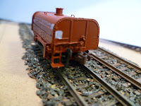
Design work on the turnouts is on going. I found a couple a faults which are now fixed. Im planning to make a turnout soon using the old fashion way of following a paper template. What i have done tho is put together a spirit design water tank. This kit is small so i was able to find some time to do it. All up it took me about 2hrs of work to do including the little extras i added. Below are some construction, painted and than weathered photos.
Click on the photo to make it bigger


Well this year been all about learning and planning. Im hoping that 2012 will be a year of construction. I hope to start building Bendigo A box area at the start of feb. Im really looking forward to that stage of bendigo. Well i like to wish everybody a merry Christmas and a happy new year. What ever you do over the holidays make it a safe one and happy modelling for 2012.
As always im always looking for photos of bendigo yard around the late 60's early 70's please send them to bendigonscale@live.com.au Please feel free to comment on anything in my blog, no question is to silly.
Design work on the turnouts is on going. I found a couple a faults which are now fixed. Im planning to make a turnout soon using the old fashion way of following a paper template. What i have done tho is put together a spirit design water tank. This kit is small so i was able to find some time to do it. All up it took me about 2hrs of work to do including the little extras i added. Below are some construction, painted and than weathered photos.
Click on the photo to make it bigger


 |
| Lightly weathered |
 |
| Lightly weathered |
Well this year been all about learning and planning. Im hoping that 2012 will be a year of construction. I hope to start building Bendigo A box area at the start of feb. Im really looking forward to that stage of bendigo. Well i like to wish everybody a merry Christmas and a happy new year. What ever you do over the holidays make it a safe one and happy modelling for 2012.
As always im always looking for photos of bendigo yard around the late 60's early 70's please send them to bendigonscale@live.com.au Please feel free to comment on anything in my blog, no question is to silly.
Tuesday, 1 November 2011
VR T Class Series 3 diesel electric
 |
| victorianrailways.net |
Well its been a busy few weeks but as posted in my last post I'm doing a three part blog on the new VR T3 that has come out from Aust-N-Rail. For some people super detailing is a process that might end up in the too hard basket, but I'm going to give it ago anyway. This is the first time Ive added detail to a loco. I have seen other people do it and Ive found by talking to them on how they have done it has given me hope that i can too do it. Most of the time its just knowing what people have used that makes the job so much better.
Super Detailing
I will talk about weathering later but first i will go through the steps on what i did to the loco and what i used.
1. Headlights
I first drill out the holes for the headlights and the marker lights. I used a .3mm drill for the maker light holes and a .4mm for the headlights. I used these sizes as i have this already in optic fire. I will talk more about this in part 2. I found drilling the hole a bit tough as the drill bit would get stuck often, i was given a tip after doing this to use a little bit of turps at the end of the drill bit. I wanted to drill out the holes first as before i weathered the loco.
2. Top of the loco
I then went to work on the top of the loco. Using photos of the loco i located and drill .2mm holes for the lift rings (made by BLMA). I also pre-sprayed them and then just super glued them into spot. I than chopped up a Leslie S3L-R horn (BLMA) and than glued it back together to form the right shape for a T class. It was than painted black and glue into position via a .4mm hole. I also noticed in the photos there was a black cap sticking out of the loco near the front lift rings. I have no idea what it is but i used a brass pin head painted black to copy the look. This was also glued in position via a .4mm hole
3. Front Ends
My first plan was to rebuild the front end to set back the top half but i soon found out i that the best way i thought of doing it was going to be to make up a brass etch for it. I don't have time to do it now, maybe one day. So glued in two set of MU horses and brake pipes (BLMA). I also made up an uncoupling bar. This was made from .008" phosphor bronze wire made by Tichy train group. I took me a few goes to get the shape right. It was than painted blue and glued into position
4.The sides
I first played with the fuel tank. I added a pin head for the diesel fuel cap and a piece of .5 x .75mm styrene strip to make a fuel gauge. I then re sprayed the tank in engine black. I also wanted to add some sanding pipes. I had to be carefull with this as it could not foul a turning bogie. I first drill a .2mm hole under each sanding box and than i used and formed the .008" wire to make the pipes. It took a few goes to get it right but I'm happy with the overall look. Than painted them black and glued them into position with the holes i had made. Make sure you dont glue the pipes to the fuel tank. The tank needs be free to take apart the loco.
I did not add windows or wipers to the cab as i need it to be open for the sound to come out!


This is the look im after, well worked locos
WeatheringThis is a great topic, some people love it and others hate it. I have a simple rule for this. If the loco is to be running on a layout it should be weathered, if its going to sit behind glass all its life don't weather it.
Once again this is the first time Ive weathered something so i spent some time looking and talking about it. I found the whole process really easy to do.
So for me some of my locos will be strongly weathered and some will be lightly weathered. For this T class it was going to be strong weathered loco to come a cross a well used loco.
I first give the hole loco a wash in a mixture of india ink. I made the wash about 1 part ink to 10 parts water. Maybe a little bit weak but i gave it a couple of coats. I then used a brush, spit and black pastel and rubbed into all the grills, vents and front ends. To get the dusty look i used Floquil "Earth" and than a lighter coat of Polly scale "Mud". Both was air brushed on using a fine mist and with the brush set back a fairway from the loco. Thats all i did for weathering. I'm yet to add a coat of dullcote.
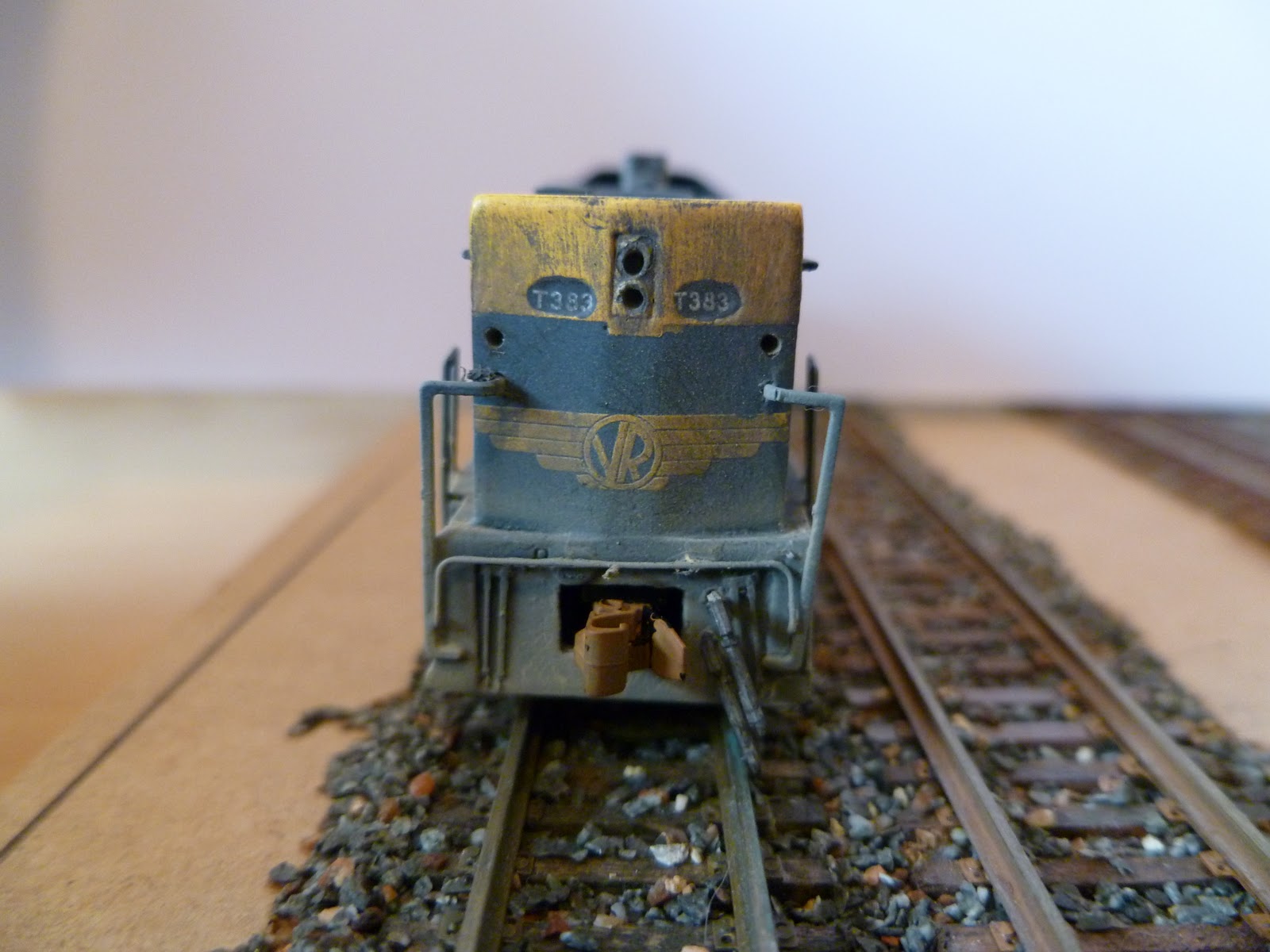
So in the end it was great fun and i found it gave the loco some life. Its not a perfect job but I'm happy with the results. I hope by reading this it may give you some ideas on what to do on your loco and guess what it wasn't that hard to do. Here are some Before and after photos of the loco. First 3 are straight out of the box and the last three are of the finish result for part one.
Remenber to click on the photo to make it bigger




I hope to get part 2 up soon. I'm just chasing a part for the marker lights but I'm hoping to get it this week.
PS. Im looking around for a CNC milling machine if anybody knows of a second hand or new one please email me a bendigonscale@live.com.au Im looking for a hobby size one.
Subscribe to:
Posts (Atom)