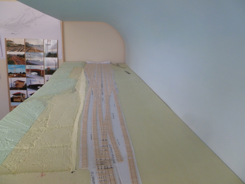
Well March has been and gone and not much was done on the layout. I had planned to finish off the etching design work and get a test run done, but my PC had other ideas. After the motherboard failed I had no PC for 3 weeks. With that and other things work etc, I only got around to doing one end of the end plates.
These are fairly easy to make by using 12mm ply wood. The trick is to make two a once so you have one already to go for the next module. To make the end boards I clamped the ply to the frame and than traced the outline of the land onto the wood. I than cut and sanded the ply to match the land form. Once I was happy with shape I than glued and screwed the ply onto the frame the same way I did the curved brackets. There was a small gap between the ply and the foam so I used a little bit of wood filler in the gap and than sanded it back. Once dry the sleepers than can be laid over the top.
With my PC now back im hoping I can finish off these etches and than get into track laying. Looking forward to making and detailing the turnouts and compounds which should provide some really good post.
Wednesday, 3 April 2013
Saturday, 9 February 2013
Landscaping Bendigo
As said in my last post i wanted a slight change in what was doing. After laying all those sleepers i wanted to do something a abit different on the layout. So i went about landscaping the front of the module. This is important as before i can my the end plates i needed to do the contour land so i can match the end plates to it. I also need to do the end plates before i can lay the rail.
I was lucky enough to find a VR map of bendigo with survey points on it. The map was done in 1929 so its a little out of date but it was going to give me a great reference on how it was. I than set a datum point on the map which was the height of the rail bed and than worked off that to get the slopes of the land. I than scaled it down to match my layout and wrote down the depth next to each point on the foam. I was also able to use the photos i took of the area to help with how the land flowed. I will put some before and after shots up in another post. There are many ways to workout how to get the depths right, but this is how i did it.
Click on photos to make them bigger
Working from the front going into the layout i slowly pushed a metal ruler into the foam to the correct depth.
From that i than cut out channels in the foam to the depth front to back. Once that was done i than used saws and hacksaw blades to cut the foam out. I found this a great way to get the slope right. Using a hacksaw blade was really good due to its fine teeth and i was flexible to match the slope needed.
At the front of the module there will be some houses along the street front so l left the land flat but it does slope down right to left to about the middle of the module were there is a small creek/drain and than goes up left to right. From there going towards the railway the land follows the same contours but also has a slope that goes up towards the yard and than there is a step embankment to go up onto the rail height. Here are some progress shot that happen along the way.
Im really happy how it has worked. It took some time to do but that was due to been careful as i wanted to get it as close to the real thing. I still have to do the back but it has a different shape than the front and doesn't go down as deep as the front. I still have to smooth off some areas and finish of road bridge end but it has been a nice change in layout construction. In these photos you can see the steep embankment going up onto the yard. Having some land shape really does change the look and feel of the layout and im really looking forward to when the scenery goes down and adds colour to it all.
Wednesday, 6 February 2013
Drilling holes for the throw bar
I thought i would give a quick how to on drilling the holes for the throw bar wire for the turnouts. I plan to use servo motors to move the the turnout blades. This is done by mounting the servo under the layout with a strong wire coming up through the baseboard and foam and than connecting to the throw bar of turnout. I good example of this is on the Tam Valley depot website. When it comes to installing the servos i will do a full how to but for now its important to drill the holes before the turnout is laid on the layout.
Its really easy to do but you do have to be careful when drilling through the foam as its really easy for the drill bit to move about. Down below are the steps.
1. Mark were to drill, you need to drill in the centre of the turnout where the throw bar is.
2. Drill a 3.5mm pilot hole slowly. Its good to set the drill on a slow speed. Drill all the way through the foam and baseboard.
3. Drill the final hole of 6.5mm. Once again drill slowly and be careful when the drill bit graps the baseboard, it can pull down on the drill.
4. Clean up the hole.
When i was laying the sleepers for the turnout i left out the sleepers near the hole as this made drilling easier. You can see in the final photo that one of the sleepers nearly covers the hole that was drilled. There is a space left for a PC sleeper to go in when the turnout is laid. I may also insert a brass tube a later date but this can be done from under the layout.
Ive also be busy forming the landscape which is making the layout look really nice. It adds so much by having hills and valleys. I will share all this in another post very soon.
Its really easy to do but you do have to be careful when drilling through the foam as its really easy for the drill bit to move about. Down below are the steps.
1. Mark were to drill, you need to drill in the centre of the turnout where the throw bar is.
2. Drill a 3.5mm pilot hole slowly. Its good to set the drill on a slow speed. Drill all the way through the foam and baseboard.
3. Drill the final hole of 6.5mm. Once again drill slowly and be careful when the drill bit graps the baseboard, it can pull down on the drill.
4. Clean up the hole.
| 1. |
| 2. |
| 3. |
When i was laying the sleepers for the turnout i left out the sleepers near the hole as this made drilling easier. You can see in the final photo that one of the sleepers nearly covers the hole that was drilled. There is a space left for a PC sleeper to go in when the turnout is laid. I may also insert a brass tube a later date but this can be done from under the layout.
Ive also be busy forming the landscape which is making the layout look really nice. It adds so much by having hills and valleys. I will share all this in another post very soon.
Tuesday, 29 January 2013
Sleepers done
Track gangers have left the site (well for a short break)
Well just coming under 4000 sleepers i have finished laying most of the sleepers on the module. Only ones needed to do are the sleepers near the end plates and also near where i have to drill the holes for the throw bar wire to come through. Once the holes are drilled i will than place those sleepers in. Some of the gaps you will see are also for the PC sleepers. From all the plans ive been able to use i have laid the sleepers to about 98% as they were in real life. In some areas there may be one or two sleepers that might not be right but this is due to having a scale of 1:160. Im very happy the way it has gone so far. Down below are the photos of the module. I love the look of the wooden sleepers, the placement and the spacing of them. (Not all in a perfect line, its my pet hate with commercial track it to straight and perfect) Once coloured and scenery is done they will blend in very nicely and look very prototypical.
Click on photo to make them bigger
Whats next?
Well im a bit track laying out for now, so im going to work on landscaping the area. This will involve getting the right heights of the hills and ditches. Ive been lucky enough to find a plan with contours on it which will help me greatly in getting the land form correct. I will also be working on some more brass etches so i can send off a final test run and i will also start the design work for the brick covert drain and the brick and stone road over bridge. I plan to make my own brick paper and stone moulds for this. Once again any one has plans or photos to share that my help email me at bendigonscale@live.com.au
Tuesday, 22 January 2013
Turnout and compound sleepers
Well ive now started laying the sleepers for the turnouts and compounds. I have been using the same method as the straight track by using jigs. These jig were laser cut by Spirit Design and have come up like a treat. Ive done a few turnouts, compounds and the two crossovers in the yard. They all take time as the sleepers are all different lengths and needs to be cut. It takes me about 15 minutes to do one. The photo with the ruler in it shows the sleepers butt joined together in the middle of the two rails. This is what happened in real life. Im now at the stage of doing a series of compounds and turnout that very close together and take awhile to lay, but its all good fun. With some of the turnouts and compounds filling in the gaps between the straight track you really do start to see the flow of the yard. I hope you enjoy the few pics below.
Click to make bigger
Monday, 31 December 2012
2000 sleepers laid!
Happy new year! Over the past couple of days ive laid over 2000 sleepers mostly all in the sidings. All the sidings are done expect where this is a turnout. Ive also done a little section of main line at the up end (melbourne end). It has a up grade of 1:126 which i have started at the road bridge. Im off to bendigo tomorrow see family and also to make a trip to the old A box site to get some photos. Im hoping this will help me out to form the landscape and also take some measurement of the brick road bridge. I hope 2013 brings great happiness to you all. Sorry for the gaps between pics i was having trouble placing the pics in the blog
Click to make bigger


Friday, 28 December 2012
Track laying starts!!
Foam Scenery
Before i could lay the first sleepers i got to lay the foam. Im using extruded polystyrene foam (XPS) This type of foam is perfect for cutting up into bits to make the scenery it is very dense but very light in weight. Make sure you don't use the common white expanded foam. It does not work. It comes off in little white balls and will only cause trouble. The XPS foam is a little bit hard to get as there are not many shops in Melbourne that sell it. It comes in many thickness as well, the colour does not matter as long its not white. To glue it down onto the layout i used a Polyurethane glue. This glue will not melt the foam but the foam has to be clamp down as the glue does expand when drying. The colour of foam is the two different thickness ive used. 30mm on the top (trackbed) and 50mm under the 30mm foam out to the side. This will help form the drop off on the side of A box. Ive also glued down my track plan in position using pva glue. The track plan was printed on one long piece of paper. The plan was drawn up in corel using my track templates. It all to 1:160 scale
Click to make bigger
Before i could lay the first sleepers i got to lay the foam. Im using extruded polystyrene foam (XPS) This type of foam is perfect for cutting up into bits to make the scenery it is very dense but very light in weight. Make sure you don't use the common white expanded foam. It does not work. It comes off in little white balls and will only cause trouble. The XPS foam is a little bit hard to get as there are not many shops in Melbourne that sell it. It comes in many thickness as well, the colour does not matter as long its not white. To glue it down onto the layout i used a Polyurethane glue. This glue will not melt the foam but the foam has to be clamp down as the glue does expand when drying. The colour of foam is the two different thickness ive used. 30mm on the top (trackbed) and 50mm under the 30mm foam out to the side. This will help form the drop off on the side of A box. Ive also glued down my track plan in position using pva glue. The track plan was printed on one long piece of paper. The plan was drawn up in corel using my track templates. It all to 1:160 scale
Click to make bigger
Track Laying
With the foam and track plan down and dried came the moment of truth time to lay the first lot of sleepers. I started to lay in the area of the two B grade sidings. These to sidings would have been hardly used, both have dead ends. These sidings would have just been kept in service not much repair work would have been done to them as traffic would have been very slow when shutting into these sidings. Keep that in mind i wanted to get a little bit of a rough look to them. It doest matter if its not straight and perfect. Its hard to see now but when it comes to colour it will stand out a bit more against the main line and other sidings. Down below is the process of laying the track.
1. Placed the sleepers in the jig.
2. Masking tape is than put onto and pressed down onto the sleepers in the jig.
3. The tape is than lifted out of the jig pulling the sleepers out holding them in position.
4. A test fit is done on the track plan to where they are going.
5. PVA glue is than applied to the area and move around with a brush.
6. The sleepers are laid into position and press down. Some areas may need a little bit of weight.
7. Once glue is dried the tape is removed.
![]() |
| 1. Sleeper placed in jig |
| 2. Tape placed on sleepers |
![]() |
| 3.Sleepers being pulled out |
| 6. Glued and weighed down |
| Drying with tape on |
![]() |
| No Tape |
There gaps left for the pc sleepers to go when the rail is laid. The pc sleepers will help hold the rail in gauge. Once all the sleepers are laid i will them colour them and than the rail can be laid. Its a easy process to do and im really looking forward to how its going to look when all the sleepers are laid. As always any questions or remarks email me at bendigonscale@live.com.au Stay tuned for more.
Subscribe to:
Posts (Atom)