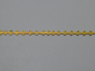
Sleeper jig
As i wanted to hand lay my track and being lots of it to lay i needed to come up with a away to be able to get great looking track but not taking a long to to build. I found the best way of building the track will be with a help of a jig. So i set out on design work on the jig. Using the VR f plans i was able to make up a design using the correct sleeper spacing for the track. One for the main line with stagered rail joints and than for sidings i would use square joints. Once the design work was done it then was laser cut by Spirit design.
Remember to click on the photos for a bigger picture
 |
| Track jig laser cut by Spirit Design |
Sleeper plates
I also wanted to have sleeper plates under the rail. I belive this will give the veiwer of the layout something more to look at. The extra detail will just finish of the scene and also give it a wow factor. Once again i knew i would lose a lot of time if i was going to have to glue each sleeper plate to each sleeper. With the spacing for the sleepers already done it was just a matter of placing the sleeper plate etch design over the slots and than joining all the sleeper plates with a connecting strip. This strip would sit under the rail and would be very hard to see. The sleeper plates have been etched from .3mm brass.
Making the track.
So putting it all togethere is really easy. It all can be done in a few simple steps. In this im building the main line with micro engineering code 55 rail but its the same procces for the yard but using code 40 rail. First i cut the rail length to the correct scaled size ( 85.72mm). I then joined the rails togethere with the etching of a joint bar on both side and than it is solded togethere. This forms a very soild joint.
Once the all rail is joined it is than solded to the sleeper plate etch. I than place pcb sleepers in the jig and the rails are than solded to the pcb. This gives it great strength. Once the gaps are filled and painted you cant tell the difference between the wooden sleepers to the pcb. Once both sides of the rail are done making sure it in gauge the whole thing is lifted out of the jig. At this point the rails and plates get there colour.
 |
| Rails and plates painted |
 |
| Rails joined to sleeper plates |
The next step is to then place the pre painted sleepers in the jig. Im using wooden sleepers from fast tracks. They come in a bag of 1000 and work really well. Once all the sleepers are in place in the jig, super glue is than runed along the under side of the rail and than place on top of the sleepers. The sleepers sit up from the jig so the rails will not glue onto the jig. Once set the whole track is lifed up out of the jig and can be glued onto the layout. Droper wires for power are solded to the under side of the rail before gluing down on the layout.
Another way of doing it would to place the sleepers in the jig and using tape place on top and lift out of jig and glue down on the layout. Remove tape afer glue has dried. Paint sleepers on layout and than place the pre gauged rail on top. Both ways work really well.
As this has been the first trail of hand laying the track ive been very happy with the results. There are a few things to fix. My etching design needs a slight improvement just to get things to sit a bit better for a better look. Im still working on colours as im not happy with the rail or sleeper colour. Trail and error is always good fun and a great lerning time. Im now working on the design work for the points which will use the same process as straight track. I will soon post on this.
 |
| A Spirit Design JX on the track |
Once again please feel free to contact me with comments, ideas or even photos of bendigo yard around the late 60's to early 70's at bendigonscale@live.com.au


