Monday, 31 December 2012

2000 sleepers laid!


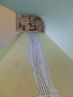
Happy new year! Over the past couple of days ive laid over 2000 sleepers mostly all in the sidings. All the sidings are done expect where this is a turnout. Ive also done a little section of main line at the up end (melbourne end). It has a up grade of 1:126 which i have started at the road bridge.  Im off to bendigo tomorrow see family and also to make a trip to the old A box site to get some photos. Im hoping this will help me out to form the landscape and also take some measurement of the brick road bridge. I hope 2013 brings great happiness to you all. Sorry for the gaps between pics i was having trouble placing the pics in the blog

Click to make bigger


Main line
Main Line at the bottom


Friday, 28 December 2012

Track laying starts!!

Foam Scenery

Before i could lay the first sleepers i got to lay the foam. Im using extruded polystyrene foam (XPS) This type of foam is perfect for cutting up into bits to make the scenery it is very dense but very light in weight.  Make sure you don't use the common white expanded foam. It does not work. It comes off in little white balls and will only cause trouble.  The XPS foam is a little bit hard to get as there are not many shops in Melbourne that sell it. It comes in many thickness as well, the colour does not matter as long its not white.  To glue it down onto the layout i used a Polyurethane glue. This glue will not melt the foam but the foam has to be clamp down as the glue does expand when drying. The colour of foam is the two different thickness ive used. 30mm on the top (trackbed) and 50mm under the 30mm foam out to the side. This will help form the drop off on the side of A box. Ive also glued down my track plan in position using pva glue.  The track plan was printed on one long piece of paper. The plan was drawn up in corel using my track templates. It all to 1:160 scale

Click to make bigger
 
 
Track Laying
 
With the foam and track plan down and dried came the moment of truth time to lay the first lot of sleepers. I started to lay in the area of the two B grade sidings. These to sidings would have been hardly used, both have dead ends. These sidings would have just been kept in service not much repair work would have been done to them as traffic would have been very slow when shutting into these sidings. Keep that in mind i wanted to get a little bit of a rough look to them. It doest matter if its not straight and perfect. Its hard to see now but when it comes to colour it will stand out a bit more against the main line and other sidings. Down below is the process of laying the track.
 
1. Placed the sleepers in the jig.
2. Masking tape is than put onto and pressed down onto the sleepers in the jig.
3. The tape is than lifted out of the jig pulling the sleepers out holding them in position.
4. A test fit is done on the track plan to where they are going.
5. PVA glue is than applied to the area and move around with a brush.
6. The sleepers are laid into position and press down. Some areas may need a little bit of weight.
7. Once glue is dried the tape is removed.


1. Sleeper placed in jig
2. Tape placed on sleepers


3.Sleepers being pulled out
6. Glued and weighed down
Drying with tape on
No Tape


There gaps left for the pc sleepers to go when the rail is laid. The pc sleepers will help hold the rail in gauge. Once all the sleepers are laid i will them colour them and than the rail can be laid. Its a easy process to do and im really looking forward to how its going to look when all the sleepers are laid. As always any questions or remarks email me at bendigonscale@live.com.au Stay tuned for more.


Tuesday, 25 December 2012

Painting a backdrop Part Two

Well after a great Christmas day, boxing day was set aside to finally get around to painting the backdrop. After many chats with people and watching youtube videos i felt i was ready to give it a another go.  The end result was good. I was very happy with it, not perfect but im more than happy the way it turned out. Now im looking really forward to it all blending in together once the scenery is done. Down below is what i did.

Click to make bigger


1. I gave the whole backdrop a undercoat in Gesso.
2. I than gave it a quick sand with 320grit  paper.
3.Now came the colour i used all acrylic based paint.  For the base i mixed Chromacryl white made by Chroma and i added Primary Blue made by Liquitex. I kept adding more blue until i got the darkest tint i wanted. Once this was done i than added a drying retarder made by Jo sonja's.
4. Using a 75mm brush that had been soaked in water for two hours i than started to paint the very top of the backdrop working all the way down to half way on the arch.
(when painting put on a medium amount of paint onto the backdrop)
5. I thank added more white to the base, mixed it in and than painted 1 1/2 brush widths across the back drop with the top part just touching the darker paint. This was repeated until i got down to the bottom.
6. I than painted a 1/2 brush width a straight white paint along the bottom.

Paint colours across the backdrop before blending

7. With a new clean brush, that also had been soaked in water (make sure you pat dry with a towel) i than lightly begin to blend in the colours. After a short time i found it best to give the brush a quick wipe to get rid of the excess paint. Keep doing this until you are happy with the blend. I than used some straight white and very lightly went over some areas. Gives the appearances of light clouds.

When painting you do have to work quickly as you dont want the paint to dry out before blending. The drying retarder does help but you still have to be quick. If it does start to dry give it a light misting of water. Its good to take a step back and have a overall look at the backdrop but dont over think it. Having some random white bits looks great. For me having a long module the colour is a little bit different from end to end but it adds more realism to the layout and also makes it look even bigger. Choosing how dark you want to go with the blue is really up to you, but i feel going lighter is better as it will bring out the trains, scenery and houses better. A good backdrop is a backdrop that brings out the models not draws the main focus onto itself.

Next its going to gluing down the foam and track plan. I than can start track laying and forming the contours of the land onto the foam. I hope this gives you something to think about next time you do a backdrop, it only one way of many on how to paint a backdrop.

Please email me at bendigonscale@live.com.au if you have questions or thoughts on this or if you have pictures or plans of bendigo in the 60-70's you are willing to share.

Tuesday, 27 November 2012

Way & Works

Today the Way & works branch received their first delivery of sleepers and rail. Hopefully the order will be enough to complete the A box module. Both rail (code 55 micro engineering ) and sleepers were bought from Fast Tracks in Canada. Below are that stats.

52.57 meters of rail
400 PC Crossover sleepers
800 PC Sleepers
2000 Wood Turnout sleepers
5000 Wood Sleepers

Thats a total of 8,200 sleepers! Happy track laying time ahead. Here is a progress photo of my Vr Y class (Spirit Design) that is in production. I will post more on this later on when i have painted and the headlights and marker lights. Click the photos to make them bigger


Monday, 19 November 2012

Painting a backdrop Part One

Well I've called this part one because it didn't work the first time around.  I'm first to stay that I'm no artist painter but i got this all wrong. Oh well. After doing all the prep working including punching the nails in, filling the holes with filler and than sanding it all back nice an smooth. I used 1200 grit sand paper for that. I was very happy with that result, i had a great surface to use. I than went and under coated it with a 3 and 1paint. Once that was dry and than went to work a painting a faded sky. A faded sky is were the sky gets darker the higher up the backdrop. This is were all the mistakes happen.

1. I used the wrong type of paint. I used house paint.
2. I used a small roller
3. I started at the top and went down. (Darker to light)

Once the paint had dried it was clear that it didn't work the way i wanted it too. It was also clear that i had the wrong shade of blue as well.  So what to do next?  After talking to family members and VNSC members I'm now armed with the right info and tips.  This is what i should have done.

1. Use a artist water based paint with a drying retarder mix in.
2. Use a good brush.
3. Start at the bottom and work my way to the top. (lighter to darker)


Before i can do all that i have to give the backdrop a good sand so that the artist paint can stick to the backdrop. A big job at hand but it will all be worth it in the end. I look forward in posting part two of this with the finished backdrop.  Other projects Ive been working on is a Spirit Design VR Y class brass loco kit. This the first time Ive put a brass loco together. I will post soon on the progress of this kit.

If you have any tips on painting backdrops please email me at bendigonscale@live.com.au or if you have and photos of bendigo yard in the 60 or 70's.

Sunday, 30 September 2012

More Construction


BUILDING THE MODULE -PART TWO
THE BACKDROP
Well more work has been done over the past two weeks with the main level baseboard down and the curved backdrop made. The baseboard is made out of 12mm ply and is just glued and screwed to the frame.  I made sure the screws were countersunked so when the foam goes on top it will be nice level.


Making the curved backdrop
I always wanted to have a curvered backdrop as i thought it made the flow from the back to top look really nice with no 90 degree joining lines at the top.  I always hoped that in the end it will help frame the layout and bring out the detail of the models in front.

The first step was to make the template of the bracket with a curved front.  The hardest part was to choose how much straight to have at the back before the curved started.  After lots of thinking and measuring i went with 160mm. The curve has a 400mm radius. After making the template i than marked out the brackets on 12mm mdf. The bracket were than cut with a jig saw and than sanded smooth.  Once all six were made i the glued and screwed them to the frame.


The backdrop is made out of 3mm mdf.  I found i piece that was 2440mm x 1200m, perfect size. Having this size meant no joining marks in the middle from using two pieces.  Bending the mdf was a effort due to it long length. It would have been easier with two people.  To help bend the mdf i use a little bit of water on the front and back were the mdf was being bent.  This helped to curve the mdf. Be careful tho too much water will destroy the mdf.  Once curved against the brackets i then nail it in place.  Glue was used along the front and once dry the excess mdf was cut off.


I'm very happy the way it has turned out. I was really worried about getting the dimensions right.  It would have been really easy make it look really small.  When you look at the layout at its future eye level height the curve backdrop really makes a fantastic finish.

Whats next?
Next is to finish the backdrop, this will include nail punching the nails, filling the holes, sanding and than painting the backdrop.  I'm really looking forward to putting some colour to the layout.  Also in the mean time I'm going to practise my cloud painting stills and also work on my secret idea i have for the backdrop?????

Once again please feel feel to ask any question or comments or if you have any photos of bendigo in 60's or 70's please email me at bendigonscale@live.com.au

Friday, 14 September 2012

Construction Begins

BUILDING THE MODULE -PART ONE
THE FRAME

Friday 14th September 2012 was a special day for bendigo, construction of the first module started.  After years and months of planing it was great to start putting it all together.  My main focus for my posts are that people with no experience in model railroads can read them and than go and build their own railways. With that in mind i will show a step by step process on how i build my railway.

Step One
Have a plan done.  This is the most important thing. Take your time in this area it will save you plenty of time in the future.  For me i have spent nearly two years planning bendigo. Most of this time was working out different templates for hand laying the track.  Once i had worked that out i was than able to draw a track plan. From the track plan i was than able to design the module. Depending on what you want to do in your model railway will depend on how long it takes you to plan it all out.

Step Two
Start building.  This is were the fun starts. Its always nice to see something in life rather than on paper.  I built the frame from qubelok 25mm square aluminium tubing. This product is made by Capral.  The tubing is a great alternative to timber as it light weight and strong. Below is the process i went through to build the frame work for the module. 

Cutting
With my plan in front of me it was time to start cutting.  To cut the tubing i used a drop down saw with a 255mm timber blade with 80 teeth.  The aluminium is soft enough to use this type of blade.  Using a metal cutting saw can be used but the metal cutting disc is proned to become full of slag very quickly.  A few things to note when measuring make sure you allow 25mm for the black plastic connectors at the ends of the tube and also don't make out along the whole tube you will lose 2 to 3mm from the blade cutting the tube. (its a very easy trap to fall into). Make sure you wear gloves, goggles and ear protection when cutting the aluminium.

Putting it all together
With all the tubes cut you will notice that there is a blur left over on the tube.  Using a flat file, file off the outside blur. Do Not file the inside blur. We want the inside blur left as it helps hold the connector in place.  The black connectors simply slide into the aluminium tubing.  Than use a rubber mallet to hammer into place. Not much force is needed for this.  Make sure you use the right connector as once they are in place they are hard to remove.


It is very easy to put all together and took me about 45mins to put the module together.  The frame does have a slight twist in it but once i screw down the ply base board it will be all square.  In Part 2 i will go through on how make the backdrop and baseboard. Please feel free to ask any question at bendigonscale@live.com.au

Click to make photos bigger


Thursday, 9 August 2012

Track plan done!

Well time has gone so quick the past few months. I finally got a copy of the Aeriel photo of bendigo yard. The best thing about it that it is in colour. In the photo you can see the newly laid track with lovely new ballast (grey area) which makes it stand out. This is going to be a great tool for modelling bendigo. The photo wasn't cheap but worth the money. Ive scan a low res copy so you can get a feel for what the photo provides me. I had to do it in low res to make it Internet friendly. I have also cropped to show just the A box area and to roughly size it make track plan area for the first module.

Click to make bigger

I have now also finish the track plan for the module which now at the printers getting printed off onto a roll. No cutting and joining the paper! I had to make some minor changes to the position of some of the turnouts in the yard in E siding as the aeriel photo showed them space a little bit different to ones on the plans i had. This meant the i will have to extend the module by 100mm but i think its really important to keep all the turnouts within the one module. There is no real spot to split the module without it been over a turnout.

With a bit of luck i will finally able to start the build very soon. Looking forward to construction, giving post on how i do things with lots of pictures.

Thursday, 28 June 2012

Aerial Photos

Well today so a trip to Victoria's land authority based in Laverton.  The purpose of this trip was to have a look at some aerial photos of the bendigo yard area. It is a great way to see where things are. eg houses, tress, dams etc.  It was really easy to find the photos i needed. They have a computer based program where you type in the info needed for the serach.  It uses melways or vicroads grid references and than you can tell it which era you need.  It than prints out a list of what film, run, negative number the photos are on. With this you take it to the desk and they will find it for you. 
Once you have it there is a small veiwing area and you can go and sit and look at the photos. The photos are taken from all different altitude ranging from 5700 feet to 22000 feet.

Note: There is a small fee for this but its really cheap.

Now i know which photo i want i will take the negative number and run to a place in Blackburn where they can print off the negative in photo quaitly.  I belive they have all the orgnial negatives there.

Now ive seem some aerial photos i can now finaly finish off the final track plan which will confirm the length of the module and i can start building. YAY. My next post will be on the first stage of construction of the module.  

Thursday, 15 March 2012

Bendigo A Box Module

Update
Well things have been very busy. I thought it would be about time to show some A box action rather than track work or models.  I plan to build bendigo in different module sizes to try and fit the yard plan in the best way. I dont want a turnout over a join of a module.  So using plans of the yard and my templates ive been drawing the yard out in scale on corel draw.  From this i now know how long to make the different modules and also how the overall layout will sit when it goes in the shed one day.  The one thing i did find is that around the B box area is going to be viewed from both sides.  Which in fact is going to work really well from one side you will see all the goods yards and from the other side you can get a great view of the engine shed (watch a loco been turned inside the shed through the window), repair shop, back platform etc. Im glad this is going to happen due to the fact it will be great to see all sides of the wonder full buildings.  The main reason for it having to being two side is for access.  It will be just to hard to get to something if it comes off by only having access on one side.

A Box Module

After downloading google sketchup 8 (freeware) i went off to make up some design work. The pictures below will tell the story but i will give a little bit of info on it.  I plan to use aluminium square cube lock system. This offers strong and light weight modules. I have seen this in use and is the only way to go now. Wood just adds up too much weight.  In the pictures below i did not draw in the black connectors but i guess you will know where they will be. 

So after looking at my plan I needed a length of 2300mm to fit in the whole of A box area including just past the bridge.  The track is width is about 350mm. I have allowed 150mm from the track to the front for the down hill slope and some landscaping. There is 150mm to the back for a road and houses.

I plan to use a photo back drop up to where the back board curves up.  I dont like having right angles on the back drop to i always was going to have it curved. I be live it just makes the layout flow better.  The actual layout will sit high almost eye height. Maybe around 1600mm or 1700mm.  Having a layout this height gives it a really good proto feel. I may in the end have a second lower level so this will help that. 

In the picture there is a signal frame. This will be on a roller draw system so it can side out, but also be pushed in under the layout. I will make the signal frame with full interlocking from modratec. Up above will be a yard diagram which will show which route is set and also have track circuits. I plan to have lights up on the top but have not sure what system i will use. I want to have a system that gives a nice day light feel but also can be change to have like a moon light effect.
The track will sit on cork and blue foam which will be glued down on the ply baseboard which will be glued and screwed into the aluminium square cube.
Remember to click on the pictures to make than bigger


Whats next?
Once i work out how to import my track plan into sketchup i will post again to show how the yard will look on the module. Im also working on an etch to iron out the bugs from the first one and hopefully when i return from a overseas holiday i will start the module building.

If you have any ideas on module building, tips and tricks all any other thoughts or question please email me at bendigonscale@live.com.au would love to hear from you.